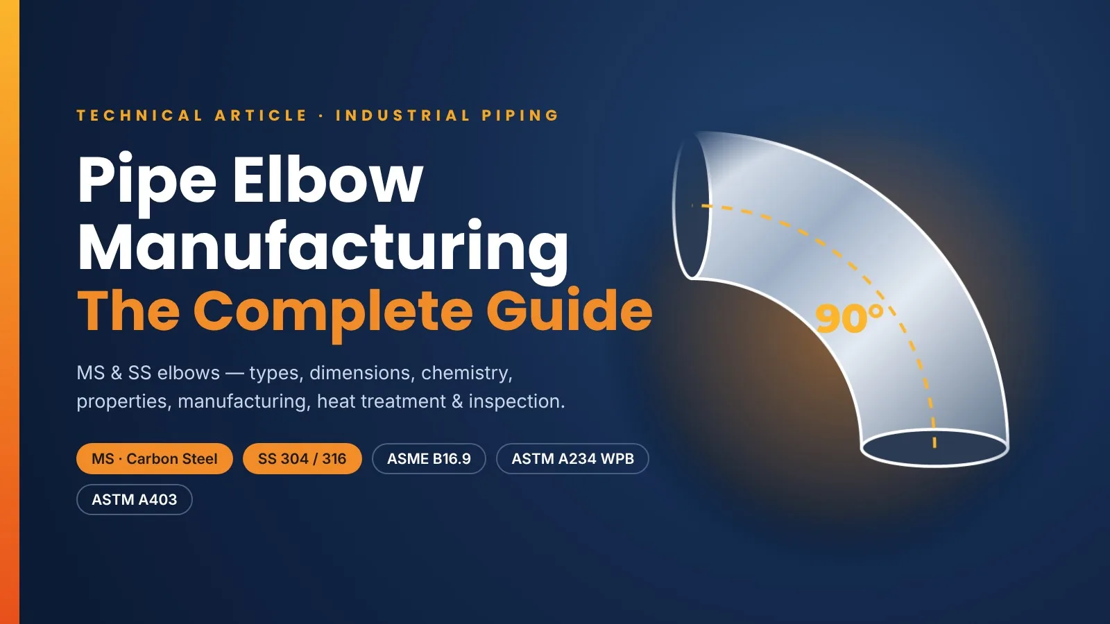
Pipe elbow manufacturing looks simple from the outside, but it is one of the most demanding jobs in the fittings trade. This complete guide covers MS & SS elbows — types, degrees, dimensions, chemical composition, mechanical & physical properties, manufacturing methods, heat treatment, inspection and traceability.
Standards covered: MS · Carbon Steel · SS 304 / 316 · ASME B16.9 · ASME B16.11 · ASTM A234 WPB · ASTM A403 · ASTM A105 / A182 · EN 10204 3.1
01. What Is a Pipe Elbow?
An elbow is a pipe fitting that changes the direction of flow in a piping system. It looks simple, but it is one of the most demanding fittings to manufacture: it must turn the flow while keeping the pipe's pressure rating, wall thickness and alignment on both ends.
Elbows are used in oil & gas, refineries, petrochemical and chemical plants, power generation, water treatment, pharmaceuticals, food processing, shipbuilding and HVAC. The two most widely used material families are MS (mild/carbon steel) for general, high-pressure and high-temperature service, and SS (stainless steel) for corrosion resistance, hygiene and low-temperature service.
| Key figure | What it means |
|---|---|
| 45° · 90° | Most common turning angles |
| 180° | Return bends for U-turns (heaters, exchangers) |
| 1.5D | Long Radius (LR) – industry default |
| ½"–48" | Butt-weld size range covered by ASME B16.9 |
02. Elbow Types: Degree, Radius & Ends
By degree
- 90° elbow – right-angle turn, the most used fitting.
- 45° elbow – gentler turn, lower pressure drop.
- 180° return – reverses flow, used in furnace coils and heat-exchanger loops.
- Other angles (30°, 60°, 22.5°) are normally cut from 90° elbows or made to order.
By radius
- Long Radius (LR): R = 1.5 × nominal size — smoother flow, less erosion.
- Short Radius (SR): R = 1.0 × nominal size — for tight spaces, higher pressure drop.
- 3D / 5D bends: larger radius, typically made as pipe bends (e.g., ASME B16.49 induction bends) for pigging lines and erosive service.
A = centre-to-end dimension · R = bend radius (centreline). The extrados (outer curve) thins during forming; the intrados (inner curve) thickens.
By end connection
| End type | Standard | Details |
|---|---|---|
| Butt-Weld (BW) | ASME B16.9 · ½"–48" | Bevelled ends welded to pipe · seamless or welded · schedules matched to pipe (Sch 5S to XXS) |
| Socket-Weld (SW) | ASME B16.11 · forged · Class 3000 / 6000 / 9000 | Pipe inserted into socket and fillet welded · small-bore, high pressure |
| Threaded (Screwed) | ASME B16.11 · forged · Class 2000 / 3000 / 6000 | NPT (ASME B1.20.1) or BSPT threads · no welding needed |
03. MS vs SS: Grades & Standards
Common Elbow Material Grades (ASTM / ASME)
| Category | Butt-Weld Elbow (wrought) | Forged Elbow (SW / Threaded) | Typical Use |
|---|---|---|---|
| MS / Carbon Steel | ASTM A234 WPB, WPC | ASTM A105 | Oil & gas, steam, water, general process |
| Low-Temp Carbon Steel | ASTM A420 WPL6 | ASTM A350 LF2 | Sub-zero service down to −46 °C |
| SS 304 / 304L | ASTM A403 WP304 / WP304L | ASTM A182 F304 / F304L | Food, pharma, water, mild chemicals |
| SS 316 / 316L | ASTM A403 WP316 / WP316L | ASTM A182 F316 / F316L | Chlorides, marine, chemicals |
| Alloy Steel | ASTM A234 WP11, WP22, WP91 | ASTM A182 F11, F22, F91 | High-temperature power & refinery lines |
| Duplex / Super Duplex | ASTM A815 S31803 / S32205 / S32750 | ASTM A182 F51 / F60 / F53 | Offshore, seawater, high strength + corrosion |
SS elbow class suffix (ASTM A403): WP-S – seamless · WP-W – welded, RT of welds made by fitting maker only where required · WP-WX – welded, 100% radiography of all welds · WP-WU – welded, 100% ultrasonic testing. Example: WP316L-S.
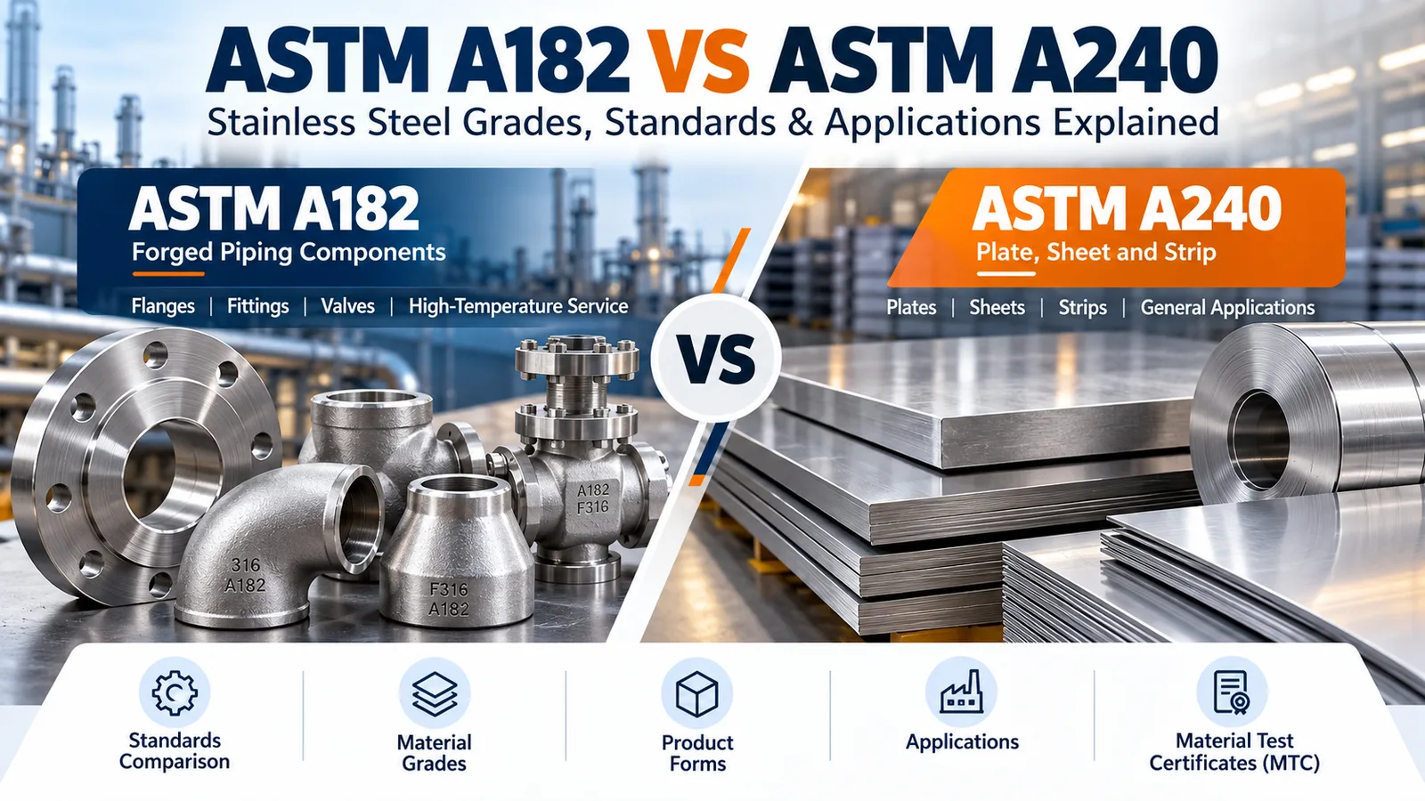
MS = Carbon steel in fittings language: In the fittings trade, "MS elbow" usually refers to carbon-steel elbows to ASTM A234 WPB (butt-weld) or ASTM A105 (forged). Many SS grades are dual-certified, e.g., WP304/304L, meeting both grades' limits. For forged grades in detail, see our guide to ASTM A182 grades explained.
04. Chemical Composition (%)
MS / Carbon Steel Elbows — Chemical Composition (wt %) · ASTM A234 WPB · ASTM A105
| Grade | C | Mn | P | S | Si | Cr | Mo | Ni | Cu | V |
|---|---|---|---|---|---|---|---|---|---|---|
| A234 WPB | 0.30 max | 0.29–1.06 | 0.050 max | 0.058 max | 0.10 min | 0.40 max | 0.15 max | 0.40 max | 0.40 max | 0.08 max |
| A105 | 0.35 max | 0.60–1.05 | 0.035 max | 0.040 max | 0.10–0.35 | 0.30 max | 0.12 max | 0.40 max | 0.40 max | 0.08 max |
Residual-element limits apply: the sum of Cu + Ni + Cr + Mo shall not exceed 1.00% (with further sub-limits per the standard). Balance: Iron (Fe).
SS Elbows — Chemical Composition (wt %) · ASTM A403 (BW) · ASTM A182 (forged)
| Grade | C | Mn | P | S | Si | Cr | Ni | Mo |
|---|---|---|---|---|---|---|---|---|
| WP304 / F304 | 0.08 max | 2.00 max | 0.045 max | 0.030 max | 1.00 max | 18.0–20.0 | 8.0–11.0 | — |
| WP304L / F304L | 0.030 max | 2.00 max | 0.045 max | 0.030 max | 1.00 max | 18.0–20.0 | 8.0–12.0 | — |
| WP316 / F316 | 0.08 max | 2.00 max | 0.045 max | 0.030 max | 1.00 max | 16.0–18.0 | 10.0–14.0 | 2.00–3.00 |
| WP316L / F316L | 0.030 max | 2.00 max | 0.045 max | 0.030 max | 1.00 max | 16.0–18.0 | 10.0–14.0 | 2.00–3.00 |
"L" grades (low carbon ≤ 0.030%) resist sensitization after welding. Mo in 316/316L improves pitting resistance in chloride service. Minor differences exist between A403 and A182 tables (e.g., Ni range of F304); always check the edition specified in the PO.
05. Mechanical Properties
Mechanical Properties — MS vs SS Elbows (minimum unless stated)
| Grade | Tensile Strength (MPa) | Yield Strength (MPa) | Elongation (%) | Hardness |
|---|---|---|---|---|
| A234 WPB | 415 – 585 | 240 min | 22 min* | 197 HB max |
| A105 | 485 min | 250 min | 22 min | 187 HB max |
| WP304 / WP316 | 515 min | 205 min | 28 min* | — |
| WP304L / WP316L | 485 min | 170 min | 28 min* | — |
*Longitudinal, standard round specimen. Transverse values are lower — refer to ASTM A234 / A403 tables. A105 also requires reduction of area ≥ 30%. 1 MPa ≈ 145 psi.
06. Physical Properties
Physical Properties — Typical Values at Room Temperature (indicative)
| Property | MS / Carbon Steel | SS 304 / 304L | SS 316 / 316L |
|---|---|---|---|
| Density | 7.85 g/cm³ | ≈ 7.93 g/cm³ | ≈ 8.00 g/cm³ |
| Melting range | ≈ 1425 – 1540 °C | ≈ 1400 – 1450 °C | ≈ 1375 – 1400 °C |
| Modulus of elasticity | ≈ 200 – 210 GPa | ≈ 193 GPa | ≈ 193 GPa |
| Thermal conductivity (100 °C) | ≈ 50 W/m·K | ≈ 16.2 W/m·K | ≈ 16.3 W/m·K |
| Thermal expansion (0–100 °C) | ≈ 11.7 µm/m·°C | ≈ 17.2 µm/m·°C | ≈ 15.9 µm/m·°C |
| Specific heat | ≈ 0.47 kJ/kg·K | ≈ 0.50 kJ/kg·K | ≈ 0.50 kJ/kg·K |
| Electrical resistivity | ≈ 0.17 µΩ·m | ≈ 0.72 µΩ·m | ≈ 0.74 µΩ·m |
| Magnetic | Yes (ferromagnetic) | No when annealed* | No when annealed* |
| Corrosion resistance | Low – needs coating/paint | Good | Very good (chlorides) |
*Austenitic SS can become slightly magnetic after cold working or near welds. SS expands ~45% more than carbon steel — important for thermal stress in mixed systems.
07. Butt-Weld Elbow Dimensions (mm)
90° · 45° · 180° Elbow Dimensions · ASME B16.9 · mm
| NPS (inch) | DN | OD at Bevel | 90° LR (A) | 90° SR (A) | 45° LR (B) | 180° LR Centre-to-Centre (O) | 180° LR Back-to-Face (K) |
|---|---|---|---|---|---|---|---|
| ½ | 15 | 21.3 | 38 | — | 16 | 76 | 48 |
| ¾ | 20 | 26.7 | 38 | — | 19 | 76 | 51 |
| 1 | 25 | 33.4 | 38 | 25 | 22 | 76 | 56 |
| 1¼ | 32 | 42.2 | 48 | 32 | 25 | 95 | 70 |
| 1½ | 40 | 48.3 | 57 | 38 | 29 | 114 | 83 |
| 2 | 50 | 60.3 | 76 | 51 | 35 | 152 | 106 |
| 2½ | 65 | 73.0 | 95 | 64 | 44 | 190 | 132 |
| 3 | 80 | 88.9 | 114 | 76 | 51 | 229 | 159 |
| 3½ | 90 | 101.6 | 133 | 89 | 57 | 267 | 184 |
| 4 | 100 | 114.3 | 152 | 102 | 64 | 305 | 210 |
| 5 | 125 | 141.3 | 190 | 127 | 79 | 381 | 262 |
| 6 | 150 | 168.3 | 229 | 152 | 95 | 457 | 313 |
| 8 | 200 | 219.1 | 305 | 203 | 127 | 610 | 414 |
| 10 | 250 | 273.1 | 381 | 254 | 159 | 762 | 517 |
| 12 | 300 | 323.9 | 457 | 305 | 190 | 914 | 619 |
| 14 | 350 | 355.6 | 533 | 356 | 222 | 1067 | 711 |
| 16 | 400 | 406.4 | 610 | 406 | 254 | 1219 | 813 |
| 18 | 450 | 457 | 686 | 457 | 286 | 1372 | 914 |
| 20 | 500 | 508 | 762 | 508 | 318 | 1524 | 1016 |
| 24 | 600 | 610 | 914 | 610 | 381 | 1829 | 1219 |
LR: A ≈ 1.5 × NPS × 25.4 (½" and ¾" use 38 mm). SR: A = 1.0 × NPS × 25.4. B16.9 covers sizes up to 48"; larger sizes follow the same rule. Verify against the latest edition before fabrication.
08. Elbow Wall Thickness (mm)
Butt-weld elbows are ordered to the same wall thickness as the pipe they join. Common schedules per ASME B36.10M (carbon) and B36.19M (stainless "S" schedules):
Nominal Wall Thickness by Schedule · ASME B36.10M / B36.19M · mm
| NPS | Sch 10S | Sch 40 | Sch 80 | Sch 160 |
|---|---|---|---|---|
| ½ | 2.11 | 2.77 | 3.73 | 4.78 |
| ¾ | 2.11 | 2.87 | 3.91 | 5.56 |
| 1 | 2.77 | 3.38 | 4.55 | 6.35 |
| 1¼ | 2.77 | 3.56 | 4.85 | 6.35 |
| 1½ | 2.77 | 3.68 | 5.08 | 7.14 |
| 2 | 2.77 | 3.91 | 5.54 | 8.74 |
| 2½ | 3.05 | 5.16 | 7.01 | 9.53 |
| 3 | 3.05 | 5.49 | 7.62 | 11.13 |
| 4 | 3.05 | 6.02 | 8.56 | 13.49 |
| 5 | 3.40 | 6.55 | 9.53 | 15.88 |
| 6 | 3.40 | 7.11 | 10.97 | 18.26 |
| 8 | 3.76 | 8.18 | 12.70 | 23.01 |
| 10 | 4.19 | 9.27 | 15.09 | 28.58 |
| 12 | 4.57 | 10.31 | 17.48 | 33.32 |
| 14 | 4.78 | 11.13 | 19.05 | 35.71 |
| 16 | 4.78 | 12.70 | 21.44 | 40.49 |
| 18 | 4.78 | 14.27 | 23.83 | 45.24 |
| 20 | 5.54 | 15.09 | 26.19 | 50.01 |
| 24 | 6.35 | 17.48 | 30.96 | 59.54 |
Sch 40/80 above are carbon-steel values (B36.10M). Up to 10", SS Sch 40S/80S are the same; from 12" up, 40S = 9.53 mm and 80S = 12.70 mm.
Key rule: Under ASME B16.9, the wall thickness at any point of the elbow must be at least 87.5% of the nominal wall. The extrados (outer curve) is where this is most at risk — always check it with an ultrasonic thickness gauge.
09. Dimensional Tolerances (mm)
Butt-Weld Elbow Tolerances · ASME B16.9 · mm
| NPS | OD at Bevel | ID at End | Centre-to-End (A, B) | 180° Centre-to-Centre (O) | Off-Angle (Q) | Off-Plane (P) |
|---|---|---|---|---|---|---|
| ½ – 2½ | +1.6 / −0.8 | ±0.8 | ±2 | ±6 | 1 | 2 |
| 3 – 4 | ±1.6 | ±1.6 | ±2 | ±6 | 1 | 2 |
| 5 – 8 | +2.4 / −1.6 | ±1.6 | ±2 | ±6 | 2 | 4 |
| 10 – 12 | +4.0 / −3.2 | ±3.2 | ±2 | ±10 | 3 | 5 |
| 14 – 16 | +4.0 / −3.2 | ±3.2 | ±2 | ±10 | 3 | 6 |
| 18 | +4.0 / −3.2 | ±3.2 | ±2 | ±10 | 4 | 10 |
| 20 – 24 | +6.4 / −4.8 | ±4.8 | ±2 | ±10 | 4 | 10 |
Wall thickness: not less than 87.5% of nominal. Values summarised from ASME B16.9 tolerance table — confirm against the edition in your purchase order.
10. Bevel Angle, Socket-Weld & Threaded
Weld bevel — ASME B16.25
- Wall ≤ 22 mm: 37.5° ± 2.5° bevel, root face 1.6 ± 0.8 mm.
- Wall > 22 mm: compound bevel — 37.5° up to 19 mm depth, then 10° ± 1°.
- Thin wall: square cut or slight chamfer at manufacturer's option.
- Ends must be square to the axis so the weld gap stays uniform all around.
Other angles from a 90° LR elbow
Aθ = R × tan(θ / 2)
Example: 60° cut from a 4" LR elbow → R = 152.4 mm → A = 152.4 × tan 30° ≈ 88 mm. For 45°: 152.4 × tan 22.5° ≈ 63 mm (B16.9 lists 64).
Forged elbows — Class vs pipe schedule & socket-weld dimensions
ASME B16.11 · mm
| End Type | Class 2000 | Class 3000 | Class 6000 | Class 9000 |
|---|---|---|---|---|
| Socket-Weld — matching pipe | — | Sch 80 | Sch 160 | XXS |
| Threaded — matching pipe | Sch 80 | Sch 160 | XXS | — |
| NPS | ½ | ¾ | 1 | 1¼ | 1½ | 2 |
|---|---|---|---|---|---|---|
| SW 90° — Centre to bottom of socket (A), Class 3000 | 15.5 | 19.5 | 22.5 | 27.0 | 32.0 | 38.0 |
| SW 90° — Centre to bottom of socket (A), Class 6000 | 19.5 | 22.5 | 27.0 | 32.0 | 38.0 | 41.0 |
| Minimum socket depth (J) | 10 | 13 | 13 | 13 | 13 | 16 |
B16.11 covers ⅛" to 4". Socket-weld practice: leave ~1.6 mm expansion gap between pipe end and socket bottom before welding. Threads: NPT per ASME B1.20.1 (or BSPT if specified).
11. Elbow Manufacturing Methods
The method depends on size, material, wall thickness and end type. The most common method for seamless butt-weld elbows is hot mandrel forming — the process usually seen in modern elbow manufacturing videos.
Hot mandrel forming — step by step
- Raw Pipe Check — Verify grade, size, heat no. and mill MTC. PMI check for SS.
- Blank Cutting — Pipe of smaller OD than the finished elbow is cut to a calculated length.
- Heating — Medium-frequency induction coil (or furnace) heats the blank to hot-working temperature.
- Pushing Over Mandrel — Hydraulic ram pushes the hot blank over a horn-shaped mandrel — it expands and bends at the same time.
- Sizing — Press dies correct OD, ovality and angle (hot or cold sizing).
- Heat Treatment — Normalizing for MS; solution annealing + water quench for SS.
- Surface Cleaning — Shot blasting for MS; pickling & passivation for SS.
- End Machining — Ends faced and bevelled to 37.5° on lathe / bevelling machine.
- Inspection — Dimensions, UT wall check, visual, PMI, hardness, NDT as required.
- Marking & Packing — Stamped / stencilled, anti-rust oil or paint for MS, packed in wooden cases.
Manufacturing methods compared
Indicative ranges
| Method | How it works | Typical product | Strengths / Notes |
|---|---|---|---|
| Hot mandrel forming | Heated pipe pushed over a horn mandrel | Seamless BW elbows, small to large sizes | High productivity, uniform shape; extrados thinning must be controlled |
| Cold forming / pressing | Pipe pressed or pushed in dies at room temperature | Small-size SS elbows | Smooth surface; solution annealing needed after forming |
| Plate pressing + welding | Two halves pressed from plate, then seam-welded | Large-diameter welded elbows | For sizes beyond seamless pipe range; welds need RT/UT |
| Closed-die forging | Hot bar/billet forged in dies, then machined | SW & threaded elbows (⅛"–4") | Dense grain flow, very high pressure classes |
| Induction pipe bending | Pipe locally heated by a ring coil and bent | 3D / 5D bends | Covered by ASME B16.49; used for pigging lines |
Mitred (segment-welded) bends are fabricated items and are not ASME B16.9 elbows.
12. Heat Treatment & Surface Finish
Heat Treatment & Finishing — MS vs SS (per material standard & qualified procedure)
| Stage | MS (A234 WPB / A105) | SS (A403 / A182 304 · 316) |
|---|---|---|
| Heat treatment | Normalizing (typically ~900 °C, air cool) or stress relieving at 595–690 °C, as A234 requires for the forming route | Solution annealing at ≥ 1040 °C followed by rapid cooling (water quench) |
| Purpose | Refine grain, remove forming stresses, achieve strength & hardness limits | Dissolve carbides, restore full corrosion resistance & ductility |
| Surface cleaning | Shot / sand blasting to remove scale | Pickling (acid) + passivation to restore the chromium-oxide layer |
| Protection | Anti-rust oil, black varnish or primer; bevel protected with caps | No coating needed; plastic caps; keep away from carbon-steel contamination |
| Common risk | Hardness above limit if cooled too fast | Sensitization / IGC if annealing or quenching is poor |
13. Inspection & Testing
Elbow Inspection & Test Plan · ✓ = routine · ○ = when specified
| Test / Check | What it confirms | MS | SS |
|---|---|---|---|
| Visual inspection | No cracks, laps, wrinkles, pits, scale | ✓ | ✓ |
| Dimensional check | OD, ID, centre-to-end, angle, off-plane, bevel per B16.9 / B16.25 | ✓ | ✓ |
| UT wall thickness | ≥ 87.5% nominal, especially at extrados | ✓ | ✓ |
| Chemical analysis / PMI | Correct grade (spectro / XRF) | ✓ | ✓ |
| Tensile test | Tensile, yield, elongation per heat / lot | ✓ | ✓ |
| Hardness test | Proper heat treatment (e.g., ≤ 197 HB for WPB) | ✓ | ○ |
| MPT / DPT | Surface cracks — MPT for MS, DPT for SS | ○ | ○ |
| Radiography / UT of welds | Soundness of seam welds (WP-WX / WP-WU) | ○ | ○ |
| Impact (Charpy) test | Toughness at low temperature (WPL6, LF2) | ○ | ○ |
| IGC test (ASTM A262 Prac. E) | Freedom from sensitization | — | ○ |
| Hydrostatic test | Not normally required for B16.9 fittings (design proven by proof test); only if PO specifies | ○ | ○ |
14. Common Elbow Defects & Prevention
| Defect | Cause | Prevention |
|---|---|---|
| Extrados wall thinning | Wrong blank size, excessive expansion | Correct mandrel/blank calculation, UT check at outer curve |
| Wrinkles at intrados | Uneven heating, wrong push speed | Controlled temperature & ram speed |
| Ovality / out-of-round ends | Insufficient sizing | Sizing dies, OD & ID checks at both ends |
| Off-angle / off-plane | Poor sizing or machining set-up | Angle gauges, fixture-based machining |
| Laps, folds, surface cracks | Overheating, poor mandrel surface | Mandrel maintenance, MPT/DPT, grind & re-check wall |
| Sensitization in SS | Slow cooling after annealing | Fast water quench, L-grades, IGC test when specified |
15. Marking & Test Certificates
Every elbow should carry permanent marking that links it to its test results. A typical marking includes manufacturer's name or logo, material grade, size, schedule or class, standard and heat number:
MFR-LOGO · ASTM A403 WP316L-S · 4" SCH 40S · 90° LR · ASME B16.9 · HT No. 12345
- EN 10204 Type 3.1 — Issued by the manufacturer's inspection department, independent of production. Shows heat number, chemical analysis, mechanical results, heat-treatment details and dimensional conformity.
- EN 10204 Type 3.2 — Same as 3.1, but tests are also witnessed and certificate countersigned by the purchaser's representative or a third-party inspector (TPI).
For what a complete certificate should contain, see our MTC format checklist.
16. What Buyers Should Specify
- ✓ Angle: 45° / 90° / 180°
- ✓ Radius: LR / SR / 3D / 5D
- ✓ Size (NPS / DN) and schedule or class
- ✓ Material grade (e.g., A234 WPB, A403 WP316L-S)
- ✓ Seamless or welded; RT / UT requirement
- ✓ End type: BW bevel / SW / NPT threaded
- ✓ Dimensional standard: B16.9 / B16.11 / MSS SP-43
- ✓ Heat treatment & surface finish
- ✓ Extra tests: IGC, impact, PMI, hardness
- ✓ Certificate type (3.1 / 3.2), marking, packing & delivery
Sending enquiries or quotes for elbows? Our quotation format for pipes and fittings helps you capture all of the above in one document.
Final Thoughts
An elbow is a small component with a big responsibility. Correct material, controlled forming, proper heat treatment, accurate machining and documented inspection all have to come together for it to perform safely for years under pressure and temperature.
In elbow manufacturing, precision is not just a target — it is what keeps the line aligned, the welds sound and the system safe.
What do you consider the most critical stage in elbow manufacturing — forming, heat treatment, machining or inspection?
Note: Values are summarised from the referenced ASTM / ASME / EN standards for general guidance. Physical properties are typical values. Always confirm requirements against the latest edition of the applicable standard and the purchase order.